Thanks for the order

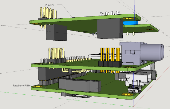
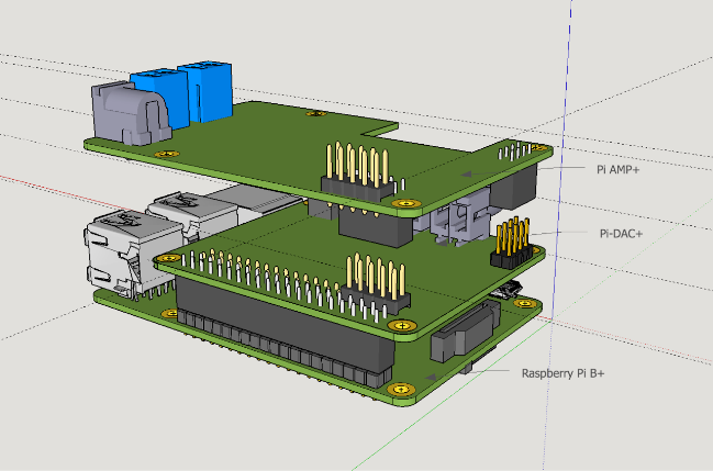
We have exposed all 40 gpio pins as a no fit pin header.
The Pi-DAC+ uses I2C (which can be shared) and GPIO22 (to mute the Pi-AMP+)
The reason we haven't populated with a pin header by default is that not everyone will want to use them - those that do can solder on the pins needed.
Our intention is that we will provide the headers as an extra item, we'll use a 2x5 male pin header for the first 10 pins then a 2x15 male right angled pin header for the remaining I/O - The right angled header is intended to be fitted beneath the Pi-DAC+ and the straight header above. Why such a strange arrangement?
Well...
Our Pi-AMP+ will fit on top of the Pi-DAC+. It'll back power the Pi / Pi-DAC+ so needs to have access to the +5v and 0v pins. Having 2 ground and 2 +5v makes sense for this. If we use the full 40 way header then we'd need to re-expose this same 40way on the Pi-AMP+ which takes a lot of board real estate which is really needed to get an optimal layout. So the amp will simply re-expose the 2x5 header and the remaining IO will be available from the Pi-DAC+.
Obviously what you want to expose and how you expose it is up to you - but if you want to use the Pi-AMP+ when it's released then this is our preferred solution.
- combination1.png (80.08 KiB) Viewed 9744 times
- combination2.png (119.77 KiB) Viewed 9744 times


